27 August 2016

More Tooling

It was another warm weekend and another great opportunity to spend time in the downstairs shop while I waited out the drying time on the flap primer. There have been two things that while I was building out the right flap that I figured I would build a jig for to make life a little easier when completing the left flap.

The first jig was a good way to machine countersink joggled flanges. The problem with doing this by hand is that even a small micro-step countersink has clearance problems getting into the angle of the joggled flange. That is, the cage hits the angle thus giving an uneven surface to countersink off of.

For this I took some 1/8" 1x2 rectangular 6061 and milled a .060 inset into it. From there I milled a 1/4 slot into that inset to accept the #40 holes (and thus the countersink pilot) from the joggled flanges.


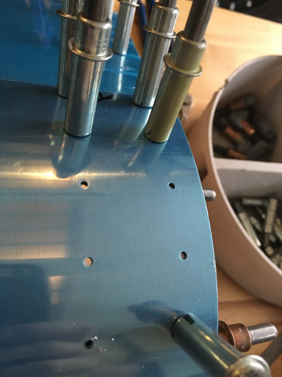
With that done, I was able to remove the cage from the micro-step countersink and use the DRO of my mill to set a zero and accurately countersink each hole to a defined depth.


The results were just what I was looking for! Excuse the scratches in the flange bracket, this was a piece of scrap.


The second jig is for the countersinking of the Trailing Edge (TE) wedges. The TE wedges need to be drilled and countersunk perpendicular to the centerline of the wedge. This is kind of annoying because well, its a wedge. You end up drilling a lot of holes and it would be nice to do this in the drill press rather than with a hand drill in order to keep all of the angles as they should be.

I started with a piece of 1/2" x 2" 6061 bar. After facing the top surface with my SuperFly I milled a 1/2" slot 1/4" deep into the bar. 


Within the main slot I put another .020 deeper slot stopping roughly .250 from each end. The idea here is that I wanted to use a piece of the trailing edge itself set into the base of the slot in order to get the angles correct. Mainly, I didn't feel like re-tramming my mill after this project so rather than set the 10 degree slope with the cutter, I cut a 0 degree slot and used a short piece of trailing edge to be used as the base of the jig.


From there, I made a little cutout to accept the micro-step countersink, hand filed the radius of the base TE corners (to accept the 1/8" radius that was left from my end-mill), and finally drilled a hole through the TE to give some clearance for the pilot of the countersink.


With that complete I was able to take the TE that I needed to countersink and set it into the jig (with the wedge in the reverse direction of the base wedge). This brings the face of the surface I need to countersink perfectly perpendicular to the countersink!


18 August 2016

Flaps: Part 2

Previous to this, I got both flap structures final drilled and began work on the right flap skins. I managed to get through the final skin to skeleton drilling pretty quickly. It took a couple of minutes to get into an efficient cleco move and drill pattern, but once I found my groove it was pretty mindless fun work (although repetitive).


There were a couple of  things that needed a little special attention. The first was the Trailing Edge final drilling the second were 2 holes on each nose rib, the third was the match drilling on the Flap Brackets.

The nose ribs come with 4 placed holes in them. The nose skins have 5 or 6. As you can see from the photo below a little of my confusion when I was blindly placing clecos and a couple holes did not line up at all. When constructing the flap I went back and forth to the manual and ended up just clecoing around those holes figuring I would find out if I had something mis-placed later (while it seemed pretty weird, I was pretty sure I had things in the correct place.


 You can see a little better from the end rib the issue at hand.


While it looks like there is a hole there, that is just a reflection of the hole that is on the vertical structure. The one thing I did not like about drilling these out is that the nose rib tabs are pretty flexible. I originally started match drilling one of the holes with my cordless drill and an older bit. You can see that it flexed the tab a little off of the skin because I was pushing a bit too hard on the drill. I went back and switch over to a brand new drill bit and my 4000RPM air drill and that made some really nice holes with no flexing on the tabs.


With all of the skin to structure holes complete I drilled the TE wedge to skin holes. This picture looked good in my mind, but is having a hard time depicting the perpendicular drill line to the centerline of the wedge.


With all of the skin holes done I started work on the Flap Brackets. This was pretty straight forward other than the bottom hole of each bracket is pretty close to the skin. Thankfully my Sioux .3HP drill motor fit into this space just fine.


Spacing out the bracket alignment with some AN4 hardware.

 That was it, all holes in the right flap are drilled. Now for some disassembly, deburring, dimpling, priming, and re-assembling!

17 August 2016

Workshop Bench Leveling

A couple of years ago I picked up 6 benches off of craigslist for basically the cost of moving them. They are 1 3/4 maple top 30x60 benches. I have had these benches in my downstairs workshop and when I started setting up the plane workspace I brought two benches up.

When I originally setup my downstairs workshop I broke one of the feet off of the table. The tables had cast feet on them and they were really brittle. Thankfully, my basement floor was dead flat so I just took off the feet and rested the bench legs straight onto the concrete. Additionally, I previously used the benches as independent work benches so I didn't really care about them lining up perfectly to each other.


Now that I have building things that fly I really wanted to make sure I could put two 60" tables next to each other and have a full 120" of solid straight and level table. Surprisingly I could not find any
"pipe feet" on McMaster. I learned that "threaded tube insert" was the search term of choice for this part. I finally found the tube inserts (search for tube not pipe) on Amazon for a decent price coming from JW Winco.


In the excitement of finding the part I was looking for I hurried through measuring things. I measured the OD of the pipe and it was 1.660".  (Looking back on this, yes, why wouldn't I measure the ID of that pipe...) I quickly hit the order button on Amazon and then went back to McMaster to order some swivel leveling feet (in retro-spect I probably didn't need the swiveling function, but they looked nice).


Two days later everything arrived. I threaded the feet into the plugs. I cleaned off the benches. It was pretty amazing how excited I was to have this level of adjustment on my tables. I tilted the benches up to put the feet in and there it was. Defeat. As in, the tables beat me yet again. The legs are thin-wall galvanized. The ID is large enough to accept the entire OD of the tube insert.


To be continued...

12 August 2016

Layout Gauge: Too warm to work on the plane

By trade I work with binary files, electronics, and disassemblers however I have a fair amount of hobby experience with metal to include mills, lathes, and welders of all kinds. If I have to lay something out I am quite comfortable with layout fluid but as we know (or so I am told) blue Dykeem, calipers, and an awl don't mix well with the thin aluminum alclad skins of the airplane that I am building in my garage.


It is August in Virginia, and it is over 100 degrees outside so tonight was a good time for a basement shop project on the mill. A layout gauge capable of holding a xtra-fine tip sharpie was tonight's project. I started with a 1/2" by 3/4" by 6" long bar of 6160 aluminum.


I faced off the end and then marked out the bars mid-point as well as .30" in from the clean face. I put a .100" hole all the way through the bar. From there I put a #1 counter bore down the hole and stopped the shoulder roughly .10" from the bottom of the bar. I realize that I have not cleaned up the rest of the faces yet, but I am fine with that for now.  


From there I followed up the hole with a 'U' bit. The sharpie has a taper on it, so I fine tuned the depth of this hole by going back and forth between taking a couple tens of thousands off and then fitting the sharpie. I was looking for the sharpie to just barely clear the base of the bar because I still intended to face off the bottom of the bar at some point.


With the sharpie fitting well it was time for the next step of the project, a ruler built into the bar. The ruler will need to be accurately located after I make the slider bar, but for now I needed to mill a channel to bring the ruler flush with the bar.


With the ruler inset into the bar, the next step was to build a sliding block that will be used as the gauge. I intended this to work like a carpenters scratch awl, but used with sharpie instead of a roller wheel or nail. I took a piece of Delrin and milled a channel into it that fit the faced off bar.


The way I laid out the slider was 2 pieces. In doing this, I was able to easily make square corners in the channel, I also wanted to put screws into the face plate of the slider that would allow me to adjust the tension of the slider (and even lock it down). In my head when I started milling I was going to put a thumb screw onto the slider (like a caliper) however at this point I like the idea of using the face screws to adjust the tension/friction.

I made a face plate to fit the slider and drilled some #43 holes in the main slider and some #33 holes in the face plate. I then counter bored the face plate holes and tapped the main slider to accept 4-40 socket head cap screws.


That was it. A fun night in a cool basement. I still have to calibrate the location of the ruler at which point I will epoxy it in place. I also have to break the edges but for now this came out just as I wanted!


11 August 2016

Flaps: Part 1

One of the interesting things about purchasing a partially completed project from someone you don't know is that you have to study their previous work and logs to get a feel for how they worked and more importantly how they documented their work. For me that was my first step in trying to figure out where to pick this project up. In my case, the Flaps and Fuel Tanks were mid-construction when I picked everything up. When I say under "construction" I mean that some of the steps for those parts had been started and I needed to take over mid-component build out.

I started by with the left flap structure clecoed, the right flap structure match drilled but disassembled, and untouched skins. After going through the logs and looking at how previous parts were completed and logged I started at step one of the Flaps, going through step by step even though they had already been complete.


When I started putting the right flap together I noticed two things:
  • There looked to be some spare parts
    • Doubler
    • Nose Rib
  • Some of the FL-1007-R plates already had their match holes drilled in them.


That left me with a bit of a problem. I went through the purchase history, but I did not see any forms for replacement doublers or ribs. I was not too concerned about this because I was pretty confident that the structure that I clecoed together was correct.  The more critical problem that I had was that when I picked up the box of components labeled flaps I did not know the order or pairing of the FL-1007-Rs. I played the game of musical flap hinge brackets but I could not for the life of me figure out a setup that perfectly aligned all the holes. You can see in the photo above about the best hole alignment I could get. I was left with a question of, were the R brackets not matched drilled (rather laid out by hand) by accident or was I just being completely dense in the matchup of components. 

I had one of two options at this point: drill out the holes and use a larger rivet or order a couple of new R brackets. This was my first contribution to the project and I had a hard time taking the path that was against the book. Speaking of books, I needed to order a new construction book anyways. The book that I had was from 2004 and I figured it would be nice to have the most current set of plans. I ended up ordering 3 new FL-1007-R brackets to replace the ones that already had been drilled out.


The brackets and new construction plans arrived  in a couple of days and after a quick replacement of the R brackets I was able to continue into new territory on the project and start clecoing the flap skins to the structure.


With the skins clecoed it was on to match drilling all of the skins to the skeleton.  I also spent a fair amount of time on the workshop getting some additional storage options.


04 August 2016

Workshop setup

One of the big questions I had prior to starting this project was did I have enough room to really accomplish this task. I put off really thinking about it because that seemed like it had the potential to be an excuse that would allow me to talk myself out of tackling this project. I really left the planning of where to work on this all the way until there was a 20ft box truck in my driveway.

The first step we took was simple. Unload the truck to see what we were dealing with. I brought everything that was going to be on my short term work list into the garage.


The components that were complete, or partially complete went down into the basement. This was not the final resting place for them, this was just where things went as they came off the truck.


The thought (at least at the current time) is that I will bring a couple of benches up from my workshop in the basement, and do the majority of the work in the garage. I plan to keep my workshop as a workshop and suspend the completed components from the ceiling in the downstairs shop. We have pretty tall ceilings, so this should work out well. 

Setting forward on that plan, I re-arranged some of the garage and started to add shelves and storage.


After bringing up some benches, the plan seems to give me ample space. Given the current components, I don't feel like I am working around anything or that anything is in the way. I have some garage clean-up to do yet. I also need to level my benches and I want to build some brackets to lock the benches together while using those brackets to also hard tie in things like a c-frame in-between the tables when needed. I will probably tackle that this weekend.


I will update this when I move my mill and hang some of the components in the downstairs shop.